BUILT IN OREGON · PROJECT 01
A DIGITAL DASH
WITH AN ’86 SOUL.
Building a purpose-made digital instrument cluster for the Suzuki Samurai—classic amber character, modern data, zero generic tablet vibes.
PROJECT PHASE02 / 04
PROTOTYPE + SIGNAL MAPPING
THE BUILD
IN NUMBERS
—PROJECT VISITS
—BUILD SUBSCRIBERS
—VENMO SUPPORTERS
Visits count once per device every 24 hours. Venmo supporters are updated manually.01 — THE MISSION
KEEP THE CHARACTER.
UPGRADE THE INFORMATION.
The Samurai deserves more than a universal gauge dropped into the dash. This project is designed around the original cluster opening, the truck’s analog inputs, and the unmistakable glow of the factory era.
02 — DEVELOPMENT ROADMAP
CURRENTLY IN PHASE 02WHAT HAPPENS
WHAT HAPPENS
FROM HERE.
The screens fit and the first interface is alive. The current job is to turn that proof of concept into measured, protected, vehicle-ready hardware.
PHASE 01COMPLETE
Concept + Fitment
Prove the idea, establish the visual direction, and confirm the displays can live inside the factory cluster.
- Define the information layout and Hybrid 1986 gauge style
- Model the dual-display rear cradle and center joiner
- Print the first mounting parts and confirm front/rear fit
- Build the first functional gauge and startup screen
PHASE 02CURRENT PHASE
Prototype + Signal Mapping
Turn the bench demo into a complete two-screen prototype and document every signal coming from the Samurai.
- Receive and bench-test the new screens and rotary control
- Finalize and order the required sensors, senders, connectors, and protection components
- Use a multimeter to identify and record ECU/vehicle input ranges for RPM, speed, fuel, coolant temperature, oil pressure, and system voltage
- Confirm discrete inputs for turn signals, high beam, brake warning, check engine, and future 2WD/4H/4L indication
- Build and test protected signal-conditioning circuits so 12-volt vehicle signals are safe for the controller
- Calibrate the simulated inputs and synchronize the Hybrid 1986 interface across both screens
PHASE 03UP NEXT
Vehicle Integration
Replace temporary bench wiring with serviceable hardware, install it in the Samurai, and calibrate against real vehicle data.
- Design the permanent interface board with fusing, reverse-polarity protection, filtering, and automotive-safe inputs
- Build a labeled, removable wiring harness without cutting the factory harness where possible
- Revise and print the final heat-resistant cradle, center section, and cable supports
- Install the complete cluster and verify ignition behavior, dimming, startup, shutdown, and parasitic draw
- Calibrate speed, RPM, fuel level, temperature, and pressure against trusted reference readings
PHASE 04FINAL PHASE
Road Validation + First Run
Prove reliability in real conditions, freeze the design, and prepare a documented small production run.
- Road-test for signal noise, vibration, heat, cold starts, glare, and nighttime brightness
- Verify warning behavior, sensor-failure states, power interruption recovery, and long-duration stability
- Finalize firmware, bill of materials, wiring diagram, printed parts, and installation guide
- Calculate the first-run cost and apply remaining donations to make the first 10 units more affordable
- Assemble and validate the first 10 units before wider production is considered
03 — PROGRESS PHOTOS
FROM SCREEN
TO WORKBENCH.
Real development photos from the first design studies through CAD, 3D printing, wiring, programming, and a working gauge prototype.
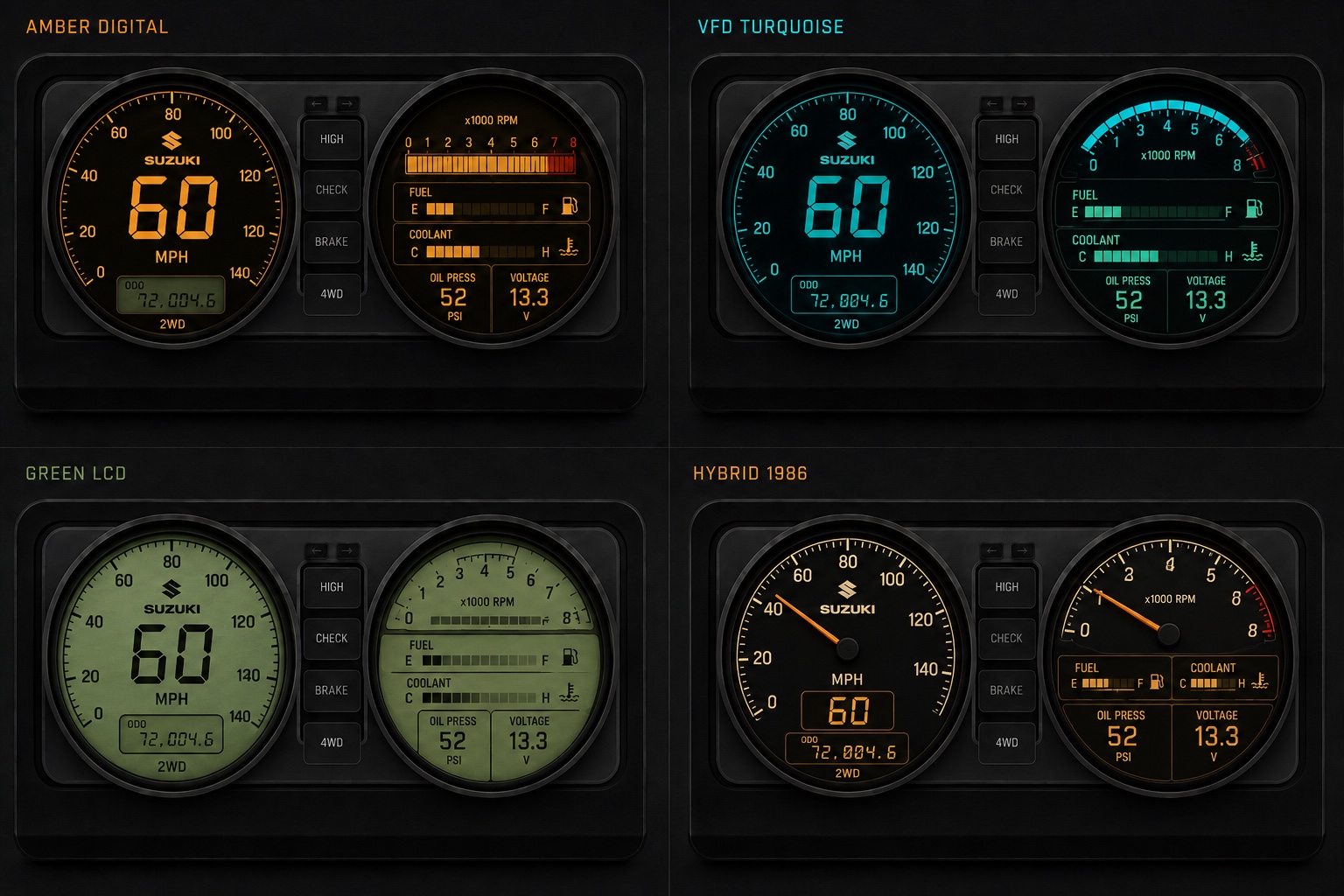
Choosing the visual language
Four early directions narrowed the look down to the warm, analog-inspired Hybrid 1986 concept.
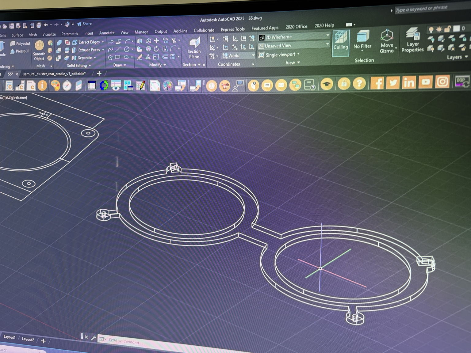
Cradle modeled in CAD
A twin-display rear cradle shaped around the Samurai cluster mounting points.
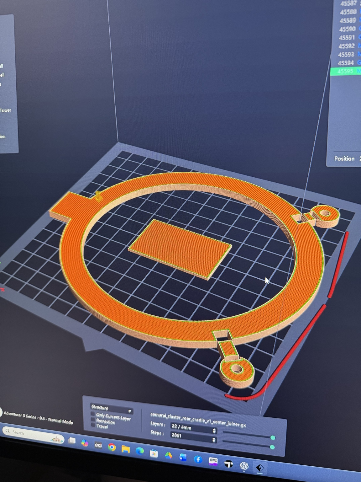
Print geometry prepared
The center section was separated and oriented for a clean prototype print.
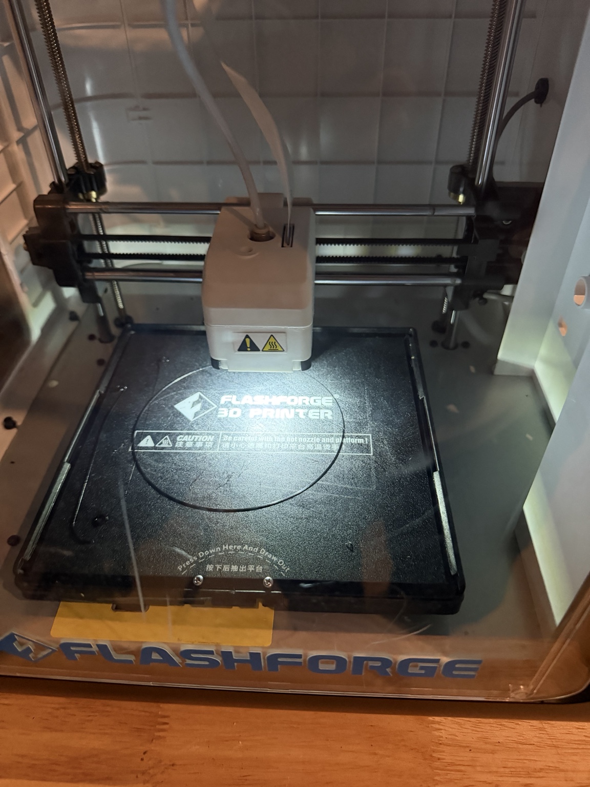
First cradle in production
The mounting hardware moved from screen to plastic for the first physical fit check.
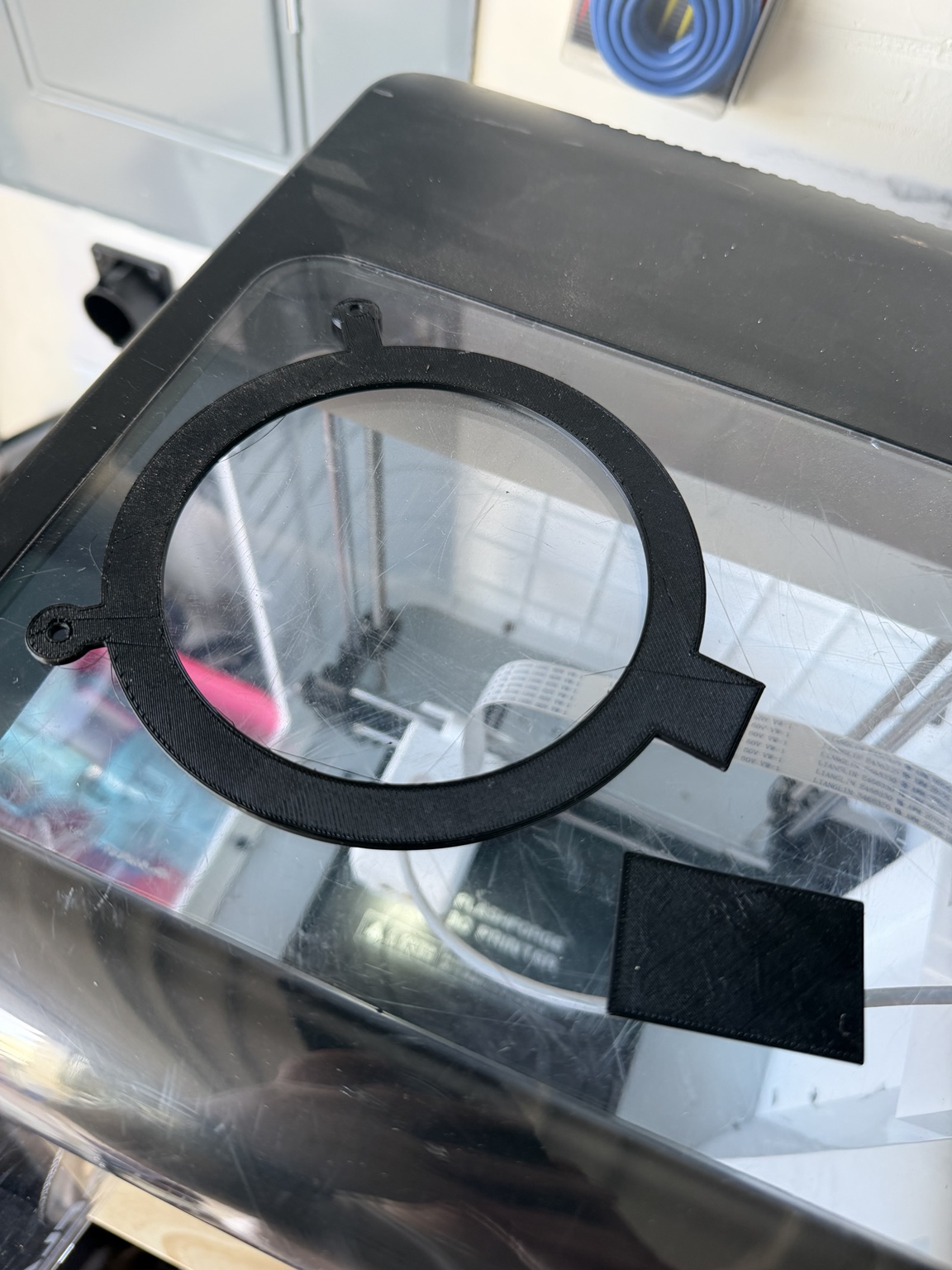
First printed parts
The circular mount and center joiner came off the printer cleanly and were ready for a real cluster test.
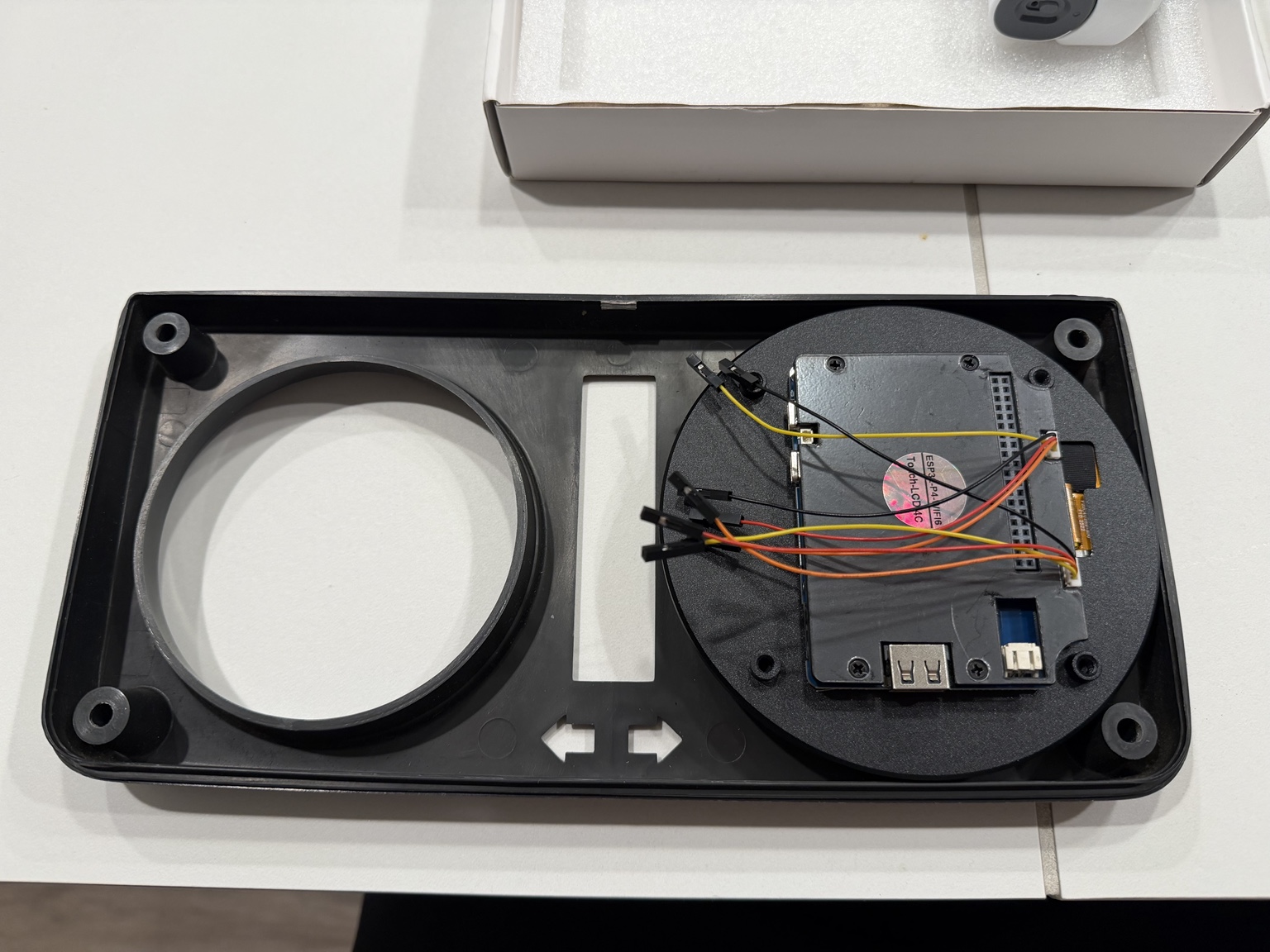
Rear fit confirmed
The display and printed cradle align with the original housing and factory mounting area.
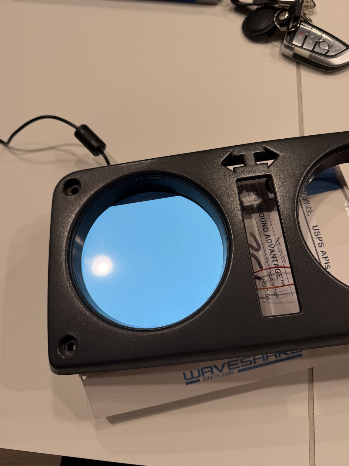
Front opening test-fit
The round screen sits cleanly inside the original gauge opening with the bezel retained.
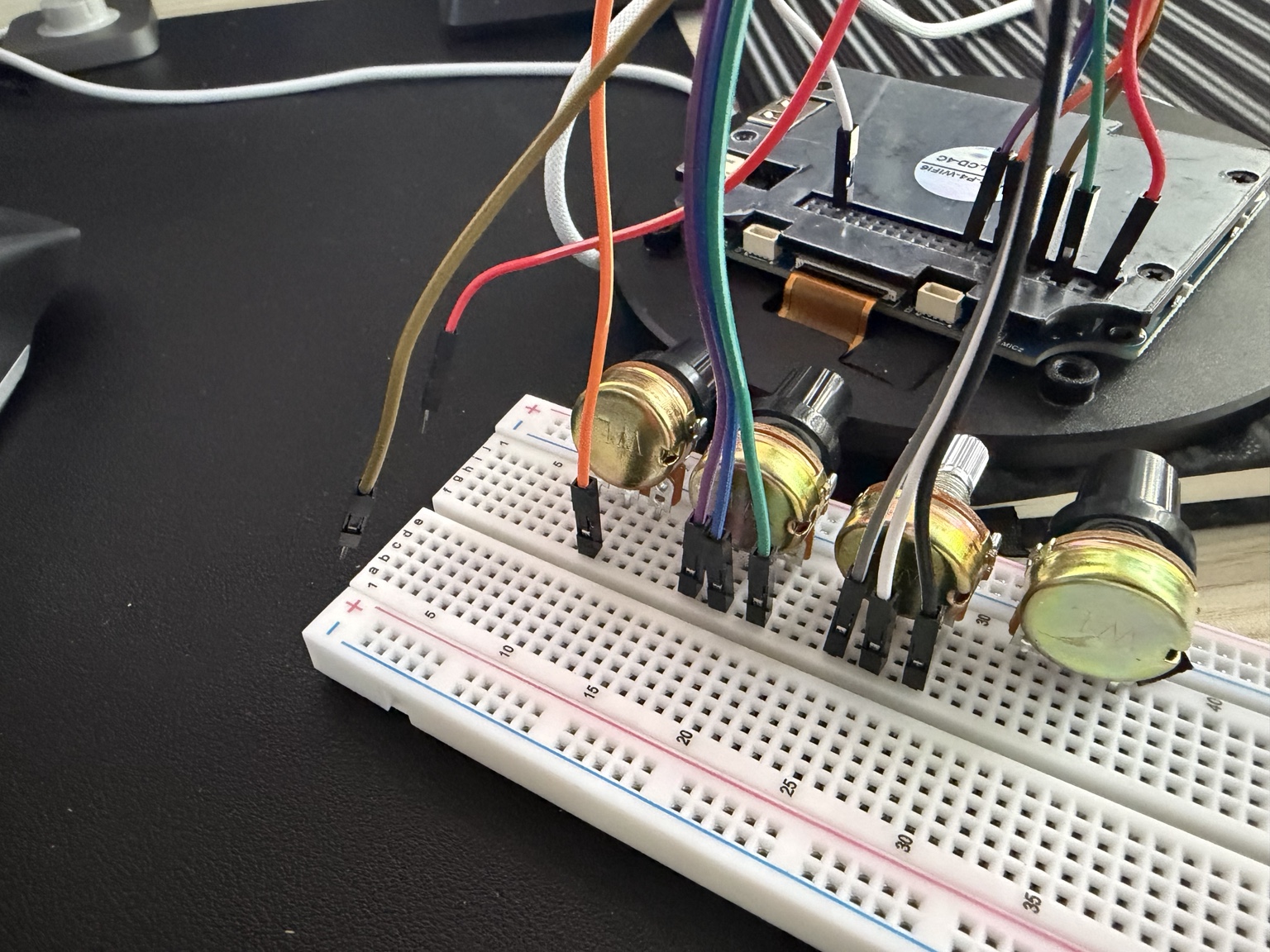
Analog inputs on the bench
Temporary controls simulate the signals the final interface board will read from the vehicle.
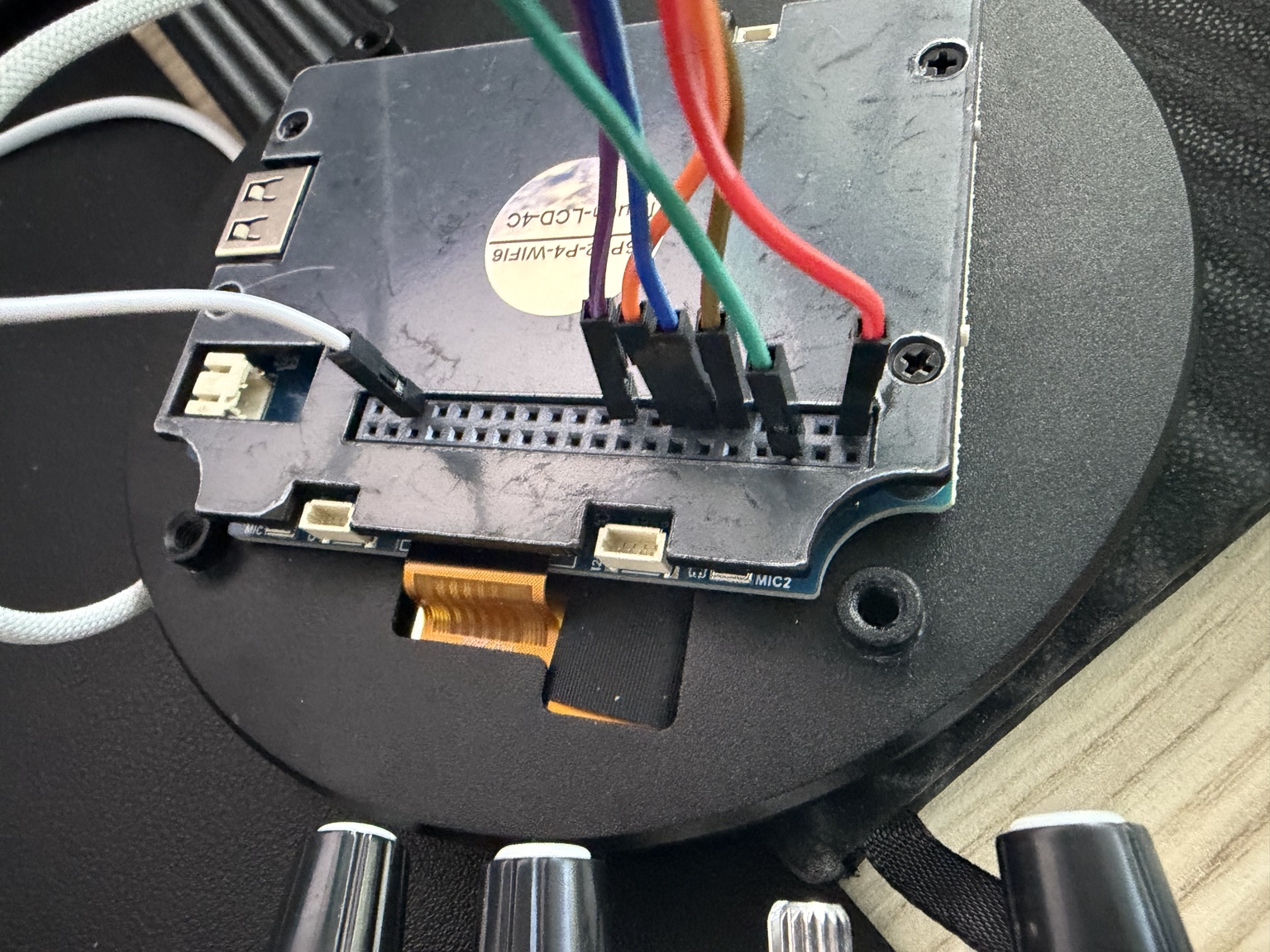
Display pinout connected
Power and signal connections were mapped before the permanent harness design.
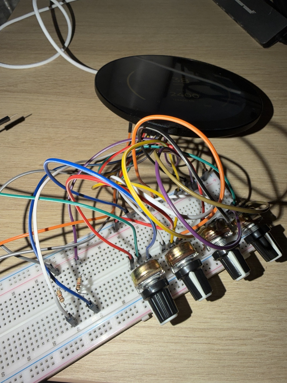
Complete bench prototype
The display, controls, and temporary wiring are working together as one test system.
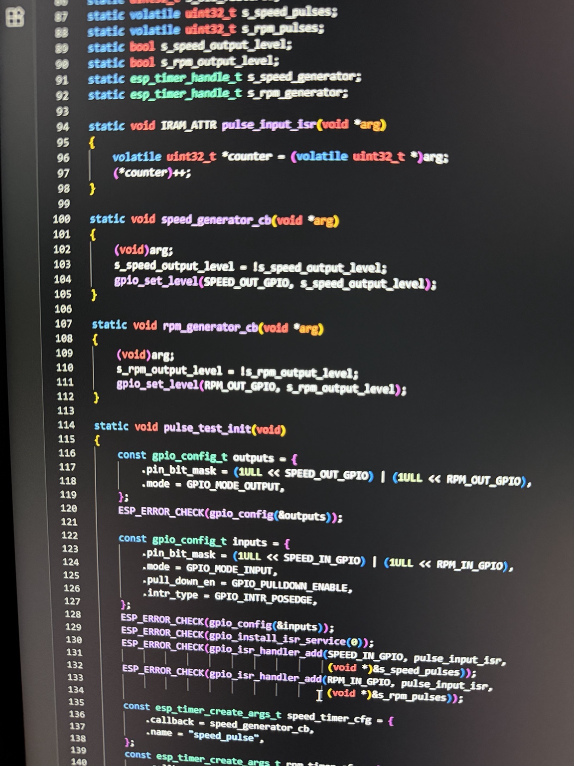
Speed and RPM signal code
Pulse generators make it possible to test gauge behavior before connecting to the Samurai.
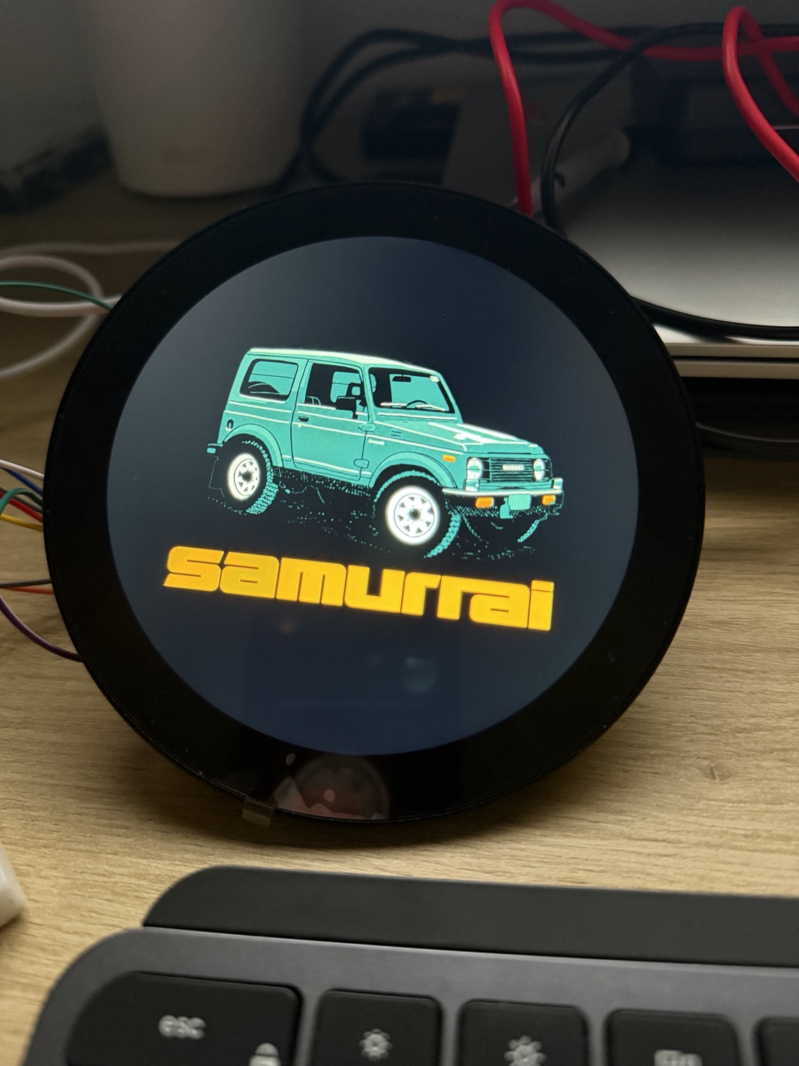
Custom startup screen
A dedicated Samurai boot screen brings personality to the power-on sequence.
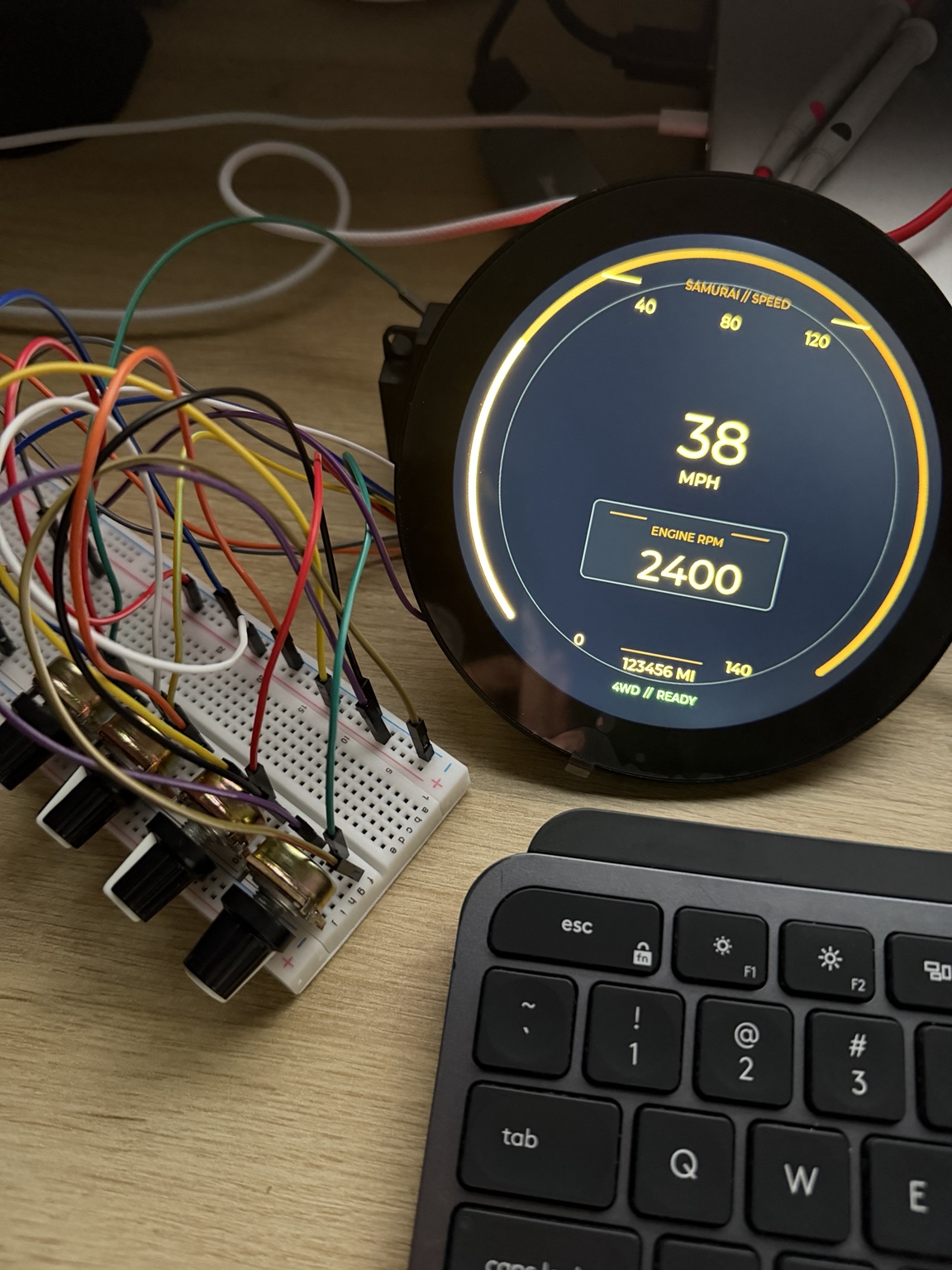
Live gauge interface
The display is now rendering speed, RPM, mileage, and four-wheel-drive status on the bench.
04 — BUILD LOG
LATEST FROM
THE GARAGE.
01
Second display and control knob ordered
The display layout is locked in. The matching screen and rotary control are on the way so bench testing can move forward.
02
Screen placement confirmed
The new display fits the Samurai cluster opening. Programming, signal testing, and the rear mounting bracket are the next major steps.
03
Project direction established
The goal: modern information with the warm amber character of a 1986 dashboard—without turning the cabin into a tablet.
05 — BACK THE BUILD
HELP TURN THE
PROTOTYPE INTO REALITY.
Every contribution goes directly toward displays, sensors, interface electronics, test hardware, and prototype materials.
THE FIRST 10 COMMITMENTOnce development costs are covered, any remaining donations will be put toward the first 10 units to make that initial run more affordable.
SUPPORT @CASCADEGARAGE Venmo opens in a new tab. Contributions support an independent personal project and are not purchases or tax-deductible donations.GARAGE DISPATCH
GET THE NEXT
BUILD UPDATE.
Major milestones only—new designs, bench-test results, and prototype progress. No clutter.